
# Custom Geometry in SceneScript
# Introduction
Wallpaper Engine does not only support importing existing 3D models, it also allows you to dynamically create them via SceneScript. Creating custom models directly via SceneScript opens up a lot of possibilities for procedural generation and dynamic audio visualizers. By utilizing the thisScene.createModelData() function, you can build 2D meshes or 3D shapes vertex by vertex entirely through code. Keep in mind that this is an advanced tutorial and you are expected to have a basic understanding of SceneScript before you continue.
In this tutorial, we will start with the very basics and move all the way up to a simple animated geometry example.
A note on AI Assistance
While geometry code can certainly be programmed by hand, we assume that many people will use AIs to assist them with the creation or review of their ideas. Whenever you work with any AI system to generate or review code, make sure to include the latest lib.sceneScript.d.ts file in your prompts. This declaration file contains helpful guidelines and prevents bad practices from making it into your code. Always make sure your code is highly optimized and do not solely rely on AI-generated code, as bad practices can lead to severe performance degradations.
# 2D vs. 3D Coordinate Systems
Before writing any code, it is critical to understand how Wallpaper Engine handles coordinates depending on your scene setup. The numbers you use to define the size of your shapes will change drastically based on your environment:
- 2D Wallpapers (Pixels): In a standard 2D wallpaper, 1 unit equals exactly 1 pixel. When placing your vertices, you will use actual pixel values (e.g.,
1920or1080). - 3D Wallpapers (Units): In a 3D scene, Wallpaper Engine uses a normalized scale. Here,
1.0is a highly useful reference size that represents one standard unit of measurement in the 3D space. Do not use large pixel values in a 3D context, or your model will be massive and clip through the camera.
# Understanding the Vertex Buffer
To build a shape, you need to provide the graphics card with a vertex buffer. This is a flat array of numbers (Float32Array) containing all the mathematical data for your points.
For a basic triangle using the standard [POSITION, NORMAL, UV] format, every single point (vertex) requires 8 numbers:
- Position (X, Y, Z): Where the point is located in the scene.
- Normal (NX, NY, NZ): Which direction the surface is facing. For flat 2D shapes facing the camera, this is almost always
0, 0, 1. - UV (U, V): The texture coordinates, mapping a 2D image to your shape on a scale from
0.0to1.0.
# Understanding the Vertex Format
The vertexFormat array is the instruction manual that tells the graphics card how to read your vertexBuffer. Because your buffer is just one long, continuous list of numbers, the engine needs to know how to chop it up into meaningful pieces for each point.
In the most basic setup, every vertex uses exactly 8 numbers. The vertexFormat tells the engine what those 8 numbers represent and in what order they appear:
IModelData.POSITION: The first 3 numbers (X, Y, Z). IModelData.NORMAL: The next 3 numbers (NX, NY, NZ). IModelData.UV: The final 2 numbers (U, V).
The most common vertexFormat is defined in this exact order and we recommend that you stick to this format:
vertexFormat: [IModelData.POSITION, IModelData.NORMAL, IModelData.UV],
The order of the constants in your vertexFormat array must exactly match the order of the numbers in your vertexBuffer. You would only change this format for special use-cases like using a material with a normal map. You can find a specific example further down below, where we add IModelData.TANGENT_SIGNED to enable the usage of a normal map.
# Geometry Example 1: Drawing A Basic Triangle
Before you get started with any code, you have to import a texture that your future model uses and you have to prepare a layer that the script can run on.
# Importing a Material for SceneScript usage
Typically, materials (textures) are assigned directly to a layer. However, when generating a model via SceneScript, there might not be a suitable material for your model. To create a new material, navigate to the Assets tab at the bottom of the editor, then right-click and select New Material. You will be prompted to type a name, afterwards, a new material will appear that you can select from the Assets tab.
Select the material, then on the right-hand side, either select an existing Albedo texture or import a new texture file that you want to use. Additionally, you may want to disable the Lighting option if you do not plan on using lights in your wallpaper. Once the material with a basic albedo texture has been created, you can move on to the next section.
A Note on Normal Maps (PBR): If you plan to use a normal map or other advanced PBR features on your custom model, your code will require an extra piece of data called a "Tangent" to calculate lighting correctly. We will stick to a basic unlit Albedo texture for now, and we will cover how to upgrade your code for Normal maps in a later section.
# Creating the Transform Layer
We recommend using a Transform Layer for the purpose of dynamic model creations. These layers allow you to attach SceneScript code to them without rendering anything on their own. To add a Transform layer, navigate to the left-hand side of the editor and click on Add Asset. Then select the Transform Layer from the list and create it. Next, click on the cogwheel next to the visibility property (in the upper right corner) of your newly created Transform layer and select "Bind SceneScript".
# Triangle Creation
Now that we have the material and transform layer in place, we can start by creating a very simple example in the form of a 600-pixel wide 2D triangle and display it in the scene:
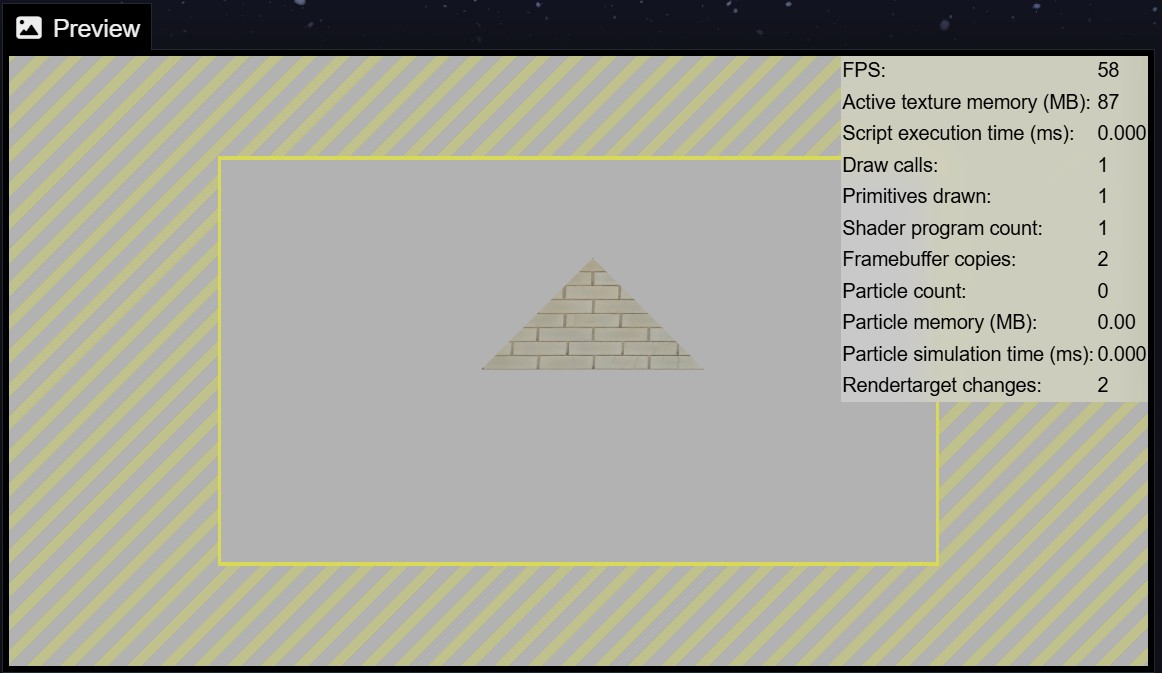
You can copy the following code, make sure to replace EXAMPLE.json at the top with the name of the material you created in the previous step:
'use strict';
const myMaterial = engine.registerAsset('materials/EXAMPLE.json', true);
export function init() {
    const triangleModel = thisScene.createModelData({
        shapes: [{
            vertexBuffer: new Float32Array([
                 0, 300, 0,    0, 0, 1,    0.5, 1.0,  // Point A: Top Center
              -300,   0, 0,    0, 0, 1,    0.0, 0.0,  // Point B: Bottom Left
               300,   0, 0,    0, 0, 1,    1.0, 0.0   // Point C: Bottom Right
            ]),
            vertexFormat: [IModelData.POSITION, IModelData.NORMAL, IModelData.UV],
            material: myMaterial,
            origin: thisLayer.origin
        }]
    });
    thisScene.createLayer({
        model: triangleModel,
        origin: new Vec3(thisLayer.origin.x, thisLayer.origin.y, thisLayer.origin.z)
    });
}
We can break this code snippet down to five steps:
- 1. Register the Material: We start by calling
engine.registerAssetin the global scope. This tells Wallpaper Engine to precache the material when the wallpaper loads (since the second parameter istrue) and allows us to assign it to our model at the time of creation. Do note that this function must be declared globally to work correctly. - 2. Use the Init Event: We place our model creation logic inside the
init()function, which runs exactly once when the wallpaper is created. It is crucial to build static models here and not in theupdate()function. Rebuilding geometry every single frame inupdate()will destroy the performance of your wallpaper. - 3. Define the Model Data: Inside
init(), we callthisScene.createModelData()to construct our 3D blueprint. We pass in ashapesarray containing ourvertexBuffer(the points of our triangle), thevertexFormat(which explains how to read the buffer), and our precachedmaterial. - 4. Construct the Vertex Buffer: The
vertexBufferis the core of your geometry. It is a single, flat array of numbers, but Wallpaper Engine reads it in chunks based on yourvertexFormat. Because our format asks for Position, Normal, and UV, every single point requires exactly 8 numbers (3 for position, 3 for normal, 2 for UV). You can clearly see the three corners of our triangle grouped in the array:- Point A (Top Center): Position
0, 300, 0| Normal0, 0, 1| UV0.5, 1.0 - Point B (Bottom Left): Position
-300, 0, 0| Normal0, 0, 1| UV0.0, 0.0 - Point C (Bottom Right): Position
300, 0, 0| Normal0, 0, 1| UV1.0, 0.0
- Point A (Top Center): Position
- 5. Create the Layer: Finally, we call
thisScene.createLayer(). By assigning our new blueprint to themodel:property, the engine instantly spawns a visible layer on the screen using our custom triangle. The triangle will be placed at the same origin as our Transform layer, since we assign itorigin: thisLayer.origin(thisLayerrefers to the Transform layer, since that is where the script is attached to).
# Geometry Example 2: Drawing a 3D Pyramid
Now that we have seen a basic 2D triangle, lets step into the third dimension. We are going to more triangles to form a simple 3D pyramid, additionally we will rotate our new model layer to create a basic animation.
If you enable the Lighting option in your material and place a Light object into your scene, you will also see how the light interacts with the 3D model.
Please note: 3D shape in a 2D wallpaper
To avoid any confusion, please be aware that 3D shapes in 2D wallpapers still use pixels as a positional unit for the vertex buffer. If you are working through this tutorial in a 3D scene, you must instead use the 1.0 reference scale for the vertex buffer.
# Building 3D Faces and Normals
A 3D object is just a collection of flat 2D triangles arranged in space. To build a square pyramid, we need 6 triangles in total: 4 for the sides, and 2 to make up the square base.
Because we want sharp, distinct edges on our pyramid, each flat side needs its own "Normal" direction facing outward. This means we cannot share corners between the sides; we have to explicitly define every single triangle face by face.
# Animating with the Update Event
To make our pyramid spin, we need to change its rotation every single frame. We do this using the update() event. However, update() does not automatically know about the layer we created inside init(). To bridge this gap, we will store our layer in a global variable. This approach simply spins the statically created model around without modifying it. In later example, we also modify the geometry of our model itself.
# Code Example: The Rotating Pyramid
Here is the complete code, be sure to adjust the material name from EXAMPLE to the material you have actually created.
'use strict';
// 1. Register assets at the root global level
let defaultMaterial = engine.registerAsset('materials/EXAMPLE.json', true);
let pyramidLayer = null;
let pyramidModel = null;
export function init(value) {
    // Define the dimensions of the pyramid
    let s = 200; // Half-size of the base
    let h = 300; // Height to the tip
    // 2. Define the vertex data: Position (3), Normal (3), UV (2)
    // A square pyramid requires 18 vertices (4 triangular sides + 2 triangles for the base)
    let vData = [
        // Front face (Normal pointing roughly 0, 0.55, 0.83)
        -s, 0,  s,   0.00, 0.55, 0.83,   0.0, 0.0,
         s, 0,  s,   0.00, 0.55, 0.83,   1.0, 0.0,
         0, h,  0,   0.00, 0.55, 0.83,   0.5, 1.0,
        // Right face (Normal pointing roughly 0.83, 0.55, 0)
         s, 0,  s,   0.83, 0.55, 0.00,   0.0, 0.0,
         s, 0, -s,   0.83, 0.55, 0.00,   1.0, 0.0,
         0, h,  0,   0.83, 0.55, 0.00,   0.5, 1.0,
        // Back face (Normal pointing roughly 0, 0.55, -0.83)
         s, 0, -s,   0.00, 0.55, -0.83,  0.0, 0.0,
        -s, 0, -s,   0.00, 0.55, -0.83,  1.0, 0.0,
         0, h,  0,   0.00, 0.55, -0.83,  0.5, 1.0,
        // Left face (Normal pointing roughly -0.83, 0.55, 0)
        -s, 0, -s,  -0.83, 0.55, 0.00,   0.0, 0.0,
        -s, 0,  s,  -0.83, 0.55, 0.00,   1.0, 0.0,
         0, h,  0,  -0.83, 0.55, 0.00,   0.5, 1.0,
        // Base triangle 1 (Normal pointing down 0, -1, 0)
        -s, 0, -s,   0.00, -1.00, 0.00,  0.0, 1.0,
         s, 0, -s,   0.00, -1.00, 0.00,  1.0, 1.0,
         s, 0,  s,   0.00, -1.00, 0.00,  1.0, 0.0,
        // Base triangle 2 (Normal pointing down 0, -1, 0)
        -s, 0, -s,   0.00, -1.00, 0.00,  0.0, 1.0,
         s, 0,  s,   0.00, -1.00, 0.00,  1.0, 0.0,
        -s, 0,  s,   0.00, -1.00, 0.00,  0.0, 0.0
    ];
    let vertexBuffer = new Float32Array(vData);
    // 3. Create the model data object
    pyramidModel = thisScene.createModelData({
        shapes: [
            {
                vertexBuffer: vertexBuffer,
                vertexFormat: [IModelData.POSITION, IModelData.NORMAL, IModelData.UV],
                material: defaultMaterial
            }
        ]
    });
    // 4. Create the custom layer at the same position as the transform layer
    pyramidLayer = thisScene.createLayer({
        name: 'Rotating Pyramid',
        model: pyramidModel,
        origin: thisLayer.origin,
        perspective: true // Enables proper 3D rendering in a 2D scene context
    });
    return value;
}
export function update(value) {
    if (pyramidLayer) {
        pyramidLayer.angles = new Vec3(0, engine.runtime * 45, 0);
    }
    return value;
}
What is noteworthy here:
- In the
createLayerfunction, we setperspective: trueto true so that Wallpaper Engine renders this 3D model layer with perspective properties. Note: You might want to lower the field of view of the scene if it causes too much of a fish-eye effect on your object. On the left-hand side of the editor, click on Scene options followed by setting the FOV slider to 45. - Notice how we save the created layer into the
pyramidLayervariable so that theupdate()function can access it later for a simple rotational animation.
# Upgrading to PBR and Normal Maps (Optional)
If you assign a material to your custom geometry that uses normal mapping or reflections, the shader requires a Tangent vector to calculate the lighting correctly. The following example video showcases a sphere with a moon texture and a moon normal map, however, the same principle applies to our pyramid from before:
To support this, first, add a normal map to your material that matches your texture. Afterwards, we have to make two specific changes to our pyramid setup:
- We need to add a tangent vector to the vertex data. A signed tangent requires 4 additional floats per vertex. The first three
(tx, ty, tz)represent the 3D direction of the tangent. The fourth float(tw)is the bitangent sign, which defines the orientation.
Inverted Y-Axis in Wallpaper Engine
You will notice that the fourth float (tw) in our new code is always set to -1.0. This is critical. In Wallpaper Engine, the texture space has an inverted Y-axis. If you set this sign to 1.0 or forget to include it, your normal maps will look inverted or completely broken as the light hits your object.
    // We added 4 floats per vertex for the tangent (tx, ty, tz) and bitangent sign (tw)
    let vData = [
        // Front face (Normal: 0, 0.55, 0.83 | Tangent: 1, 0, 0 | Sign: -1)
        -s, 0,  s,   0.00, 0.55, 0.83,   1.0, 0.0, 0.0, -1.0,   0.0, 0.0,
         s, 0,  s,   0.00, 0.55, 0.83,   1.0, 0.0, 0.0, -1.0,   1.0, 0.0,
         0, h,  0,   0.00, 0.55, 0.83,   1.0, 0.0, 0.0, -1.0,   0.5, 1.0,
        // Right face (Normal: 0.83, 0.55, 0 | Tangent: 0, 0, -1 | Sign: -1)
         s, 0,  s,   0.83, 0.55, 0.00,   0.0, 0.0, -1.0, -1.0,  0.0, 0.0,
         s, 0, -s,   0.83, 0.55, 0.00,   0.0, 0.0, -1.0, -1.0,  1.0, 0.0,
         0, h,  0,   0.83, 0.55, 0.00,   0.0, 0.0, -1.0, -1.0,  0.5, 1.0,
        // Back face (Normal: 0, 0.55, -0.83 | Tangent: -1, 0, 0 | Sign: -1)
         s, 0, -s,   0.00, 0.55, -0.83, -1.0, 0.0, 0.0, -1.0,   0.0, 0.0,
        -s, 0, -s,   0.00, 0.55, -0.83, -1.0, 0.0, 0.0, -1.0,   1.0, 0.0,
         0, h,  0,   0.00, 0.55, -0.83, -1.0, 0.0, 0.0, -1.0,   0.5, 1.0,
        // Left face (Normal: -0.83, 0.55, 0 | Tangent: 0, 0, 1 | Sign: -1)
        -s, 0, -s,  -0.83, 0.55, 0.00,   0.0, 0.0, 1.0, -1.0,   0.0, 0.0,
        -s, 0,  s,  -0.83, 0.55, 0.00,   0.0, 0.0, 1.0, -1.0,   1.0, 0.0,
         0, h,  0,  -0.83, 0.55, 0.00,   0.0, 0.0, 1.0, -1.0,   0.5, 1.0,
        // Base triangle 1 (Normal: 0, -1, 0 | Tangent: 1, 0, 0 | Sign: -1)
        -s, 0, -s,   0.00, -1.00, 0.00,  1.0, 0.0, 0.0, -1.0,   0.0, 1.0,
         s, 0, -s,   0.00, -1.00, 0.00,  1.0, 0.0, 0.0, -1.0,   1.0, 1.0,
         s, 0,  s,   0.00, -1.00, 0.00,  1.0, 0.0, 0.0, -1.0,   1.0, 0.0,
        // Base triangle 2 (Normal: 0, -1, 0 | Tangent: 1, 0, 0 | Sign: -1)
        -s, 0, -s,   0.00, -1.00, 0.00,  1.0, 0.0, 0.0, -1.0,   0.0, 1.0,
         s, 0,  s,   0.00, -1.00, 0.00,  1.0, 0.0, 0.0, -1.0,   1.0, 0.0,
        -s, 0,  s,   0.00, -1.00, 0.00,  1.0, 0.0, 0.0, -1.0,   0.0, 0.0
    ];
- We must update the vertexFormat array to include
IModelData.TANGENT_SIGNED. This must be placed exactly between the Normal and the UV constants to match Wallpaper Engine's formatting expectations:
vertexFormat: [IModelData.POSITION, IModelData.NORMAL, IModelData.TANGENT_SIGNED, IModelData.UV],
# Dynamic Geometry Updates
The examples up until this point all used static models. While this can be a viable approach, these examples could have also been generated externally and imported as model files. In this next example, we will modify the vertex buffer every frame, effectively creating dynamically morphing model. Specifically, we will generate sixteen three-dimensional audio bars, each representing one audio frequency range (from bass to treble):
We will not analyze the entire example line by line since this would blow the scope of this tutorial. Instead, we will focus on the details that relate to the dynamic model.
Click here to view the full example
'use strict';
const audioBuffers = engine.registerAudioBuffers(engine.AUDIO_RESOLUTION_16);
const audioBarsMaterial = engine.registerAsset('materials/AudioBars.json', true);
let modelData;
let modelLayer;
let vertexBuffer;
const NUM_BARS = 16;
const FLOATS_PER_VERTEX = 8; // 3 Position + 3 Normal + 2 UV
const VERTICES_PER_BAR = 24; // 6 faces * 4 vertices
const FLOATS_PER_BAR = VERTICES_PER_BAR * FLOATS_PER_VERTEX; // 192 floats per bar
const SMOOTHING_SPEED = 15;
export function init(value) {
    // Allocate memory for 16 3D boxes
    vertexBuffer = new Float32Array(NUM_BARS * FLOATS_PER_BAR);
    // 16 bars * (6 faces * 2 triangles * 3 indices)
    let indexBuffer = new Uint16Array(NUM_BARS * 36);
    let step = engine.canvasSize.x / NUM_BARS;
    let barWidth = step * 0.8;
    let barDepth = barWidth; // Make the depth equal to the width for a square pillar
    let startX = -((NUM_BARS * step) / 2) + (step / 2);
    // Generate the 3D geometry
    for (let i = 0; i < NUM_BARS; i++) {
        let vOffset = i * FLOATS_PER_BAR;
        let iOffset = i * 36;
        let xPos = startX + (i * step);
        let hw = barWidth / 2;
        let hd = barDepth / 2;
        let h = 10; // Initial base height
        // Define the 6 faces of a box.
        // n: Normal vector
        // v: The 4 corners [x_mult, y_mult, z_mult, u, v]
        // Note: Y is either 0 (bottom) or 1 (top)
        const faces = [
            { n: [0, 0, 1], v: [[-1, 0, 1, 0, 0], [1, 0, 1, 1, 0], [-1, 1, 1, 0, 1], [1, 1, 1, 1, 1]] }, // Front
            { n: [0, 0, -1], v: [[1, 0, -1, 0, 0], [-1, 0, -1, 1, 0], [1, 1, -1, 0, 1], [-1, 1, -1, 1, 1]] }, // Back
            { n: [0, 1, 0], v: [[-1, 1, 1, 0, 0], [1, 1, 1, 1, 0], [-1, 1, -1, 0, 1], [1, 1, -1, 1, 1]] }, // Top
            { n: [0, -1, 0], v: [[-1, 0, -1, 0, 0], [1, 0, -1, 1, 0], [-1, 0, 1, 0, 1], [1, 0, 1, 1, 1]] }, // Bottom
            { n: [-1, 0, 0], v: [[-1, 0, -1, 0, 0], [-1, 0, 1, 1, 0], [-1, 1, -1, 0, 1], [-1, 1, 1, 1, 1]] }, // Left
            { n: [1, 0, 0], v: [[1, 0, 1, 0, 0], [1, 0, -1, 1, 0], [1, 1, 1, 0, 1], [1, 1, -1, 1, 1]] }  // Right
        ];
        let vCursor = vOffset;
        let idxCursor = iOffset;
        let vertexIndex = i * VERTICES_PER_BAR;
        // Loop through each face and write the floats
        for (let f = 0; f < faces.length; f++) {
            let face = faces[f];
            for (let v = 0; v < 4; v++) {
                let vert = face.v[v];
                vertexBuffer[vCursor++] = xPos + (vert[0] * hw); // X
                vertexBuffer[vCursor++] = vert[1] * h;           // Y (Multiplied by 0 or 1)
                vertexBuffer[vCursor++] = vert[2] * hd;          // Z
                vertexBuffer[vCursor++] = face.n[0];             // Normal X
                vertexBuffer[vCursor++] = face.n[1];             // Normal Y
                vertexBuffer[vCursor++] = face.n[2];             // Normal Z
                vertexBuffer[vCursor++] = vert[3];               // U
                vertexBuffer[vCursor++] = vert[4];               // V
            }
            // Write the indices for the two triangles of this face (CCW winding order)
            indexBuffer[idxCursor++] = vertexIndex + 0;
            indexBuffer[idxCursor++] = vertexIndex + 1;
            indexBuffer[idxCursor++] = vertexIndex + 2;
            indexBuffer[idxCursor++] = vertexIndex + 2;
            indexBuffer[idxCursor++] = vertexIndex + 1;
            indexBuffer[idxCursor++] = vertexIndex + 3;
            vertexIndex += 4; // Move to the next 4 vertices
        }
    }
    modelData = thisScene.createModelData({
        shapes: [{
            vertexBuffer: vertexBuffer,
            indexBuffer: indexBuffer,
            material: audioBarsMaterial,
            vertexFormat: [IModelData.POSITION, IModelData.NORMAL, IModelData.UV],
            isVertexBufferDynamic: true,
        }]
    });
    // Create a layer with 3D perspective enabled
    // Layer uses Transform Layer position on X and Z axis on reference
    // but always centers the audio bars in the Scene
    modelLayer = thisScene.createLayer({
        name: '3D Audio Visualizer',
        model: modelData,
        perspective: true,
        origin: new Vec3(engine.canvasSize.x / 2, thisLayer.origin.y, thisLayer.origin.z),
        angles: new Vec3(0, 0, 0)
    });
    // Position this layer in the layer list to match the transform layer
    thisScene.sortLayer(modelLayer, thisScene.getLayerIndex(thisLayer));
    return value;
}
export function update(value) {
    for (let i = 0; i < NUM_BARS; i++) {
        let bass = audioBuffers.average[i];
        let targetHeight = 10 + (bass * 400);
        let vOffset = i * FLOATS_PER_BAR;
        // Read the current height from the very first top vertex of this bar (Front Face, Top Left)
        let currentHeight = vertexBuffer[vOffset + 17];
        // Smooth the animation
        let smoothedHeight = currentHeight + (targetHeight - currentHeight) * Math.min(engine.frametime * SMOOTHING_SPEED, 1.0);
        // Update all top vertices
        for (let v = 0; v < VERTICES_PER_BAR; v++) {
            let yIndex = vOffset + (v * FLOATS_PER_VERTEX) + 1;
            // If the Y position is greater than 0, we know it is a top vertex.
            // We update it without needing to calculate 12 different index offsets manually!
            if (vertexBuffer[yIndex] > 0) {
                vertexBuffer[yIndex] = smoothedHeight;
            }
        }
    }
    // Push the modified array to the GPU once per frame
    modelData.applyData({
        vertexBuffer: vertexBuffer,
    });
    return value;
}
There are a few things which are relevant to know to dynamically updating models. Like before, it is absolutely crucial that we create the model within the init() event and not the update event. Otherwise you would trigger the extremely heavy model creation on every frame.
Let's take a look at the model data creation in the init event first:
    modelData = thisScene.createModelData({
        shapes: [{
            vertexBuffer: vertexBuffer,
            indexBuffer: indexBuffer,
            material: audioBarsMaterial,
            vertexFormat: [IModelData.POSITION, IModelData.NORMAL, IModelData.UV],
            isVertexBufferDynamic: true,
        }]
    });
The main difference to the previous examples is that we set isVertexBufferDynamic: true here. This is necessary whenever you plan to update the vertex buffer later on. Failing to supply this parameter if you update the vertex buffer will cause an error to be thrown. We are not updating the index buffer in our example, however, if we did, then we would also need to set isIndexBufferDynamic: true in the model creation call.
Next, there really is only one more detail that differs from our previous examples: Updating the vertices. This has to happen every frame in the global update event. Inside the global update event, you simply call the applyData() function on your ModelData object and supply it with the new vertexBuffer inside of an object: { vertexBuffer: vertexBuffer, }. This will re-render the geometry immediately in a highly performant manner:
export function update(value) {
// [...] Vertex buffer modification logic goes here
modelData.applyData({
        vertexBuffer: vertexBuffer,
    });
    return value;
}
You can supply a shapes array to modelData.applyData() if needed, however, you can also omit the array it if you only have one shape (like in our example). You should generally always minimize any workload in the global update() event loop and always re-use existing objects (like the vertexBuffer), simply update existing data inside of it.
# ModelData::replaceData() functionality
If your script needs to completely swap out the model data with different, potentially incompatible data (such as adding or removing shapes, or changing buffer lengths), you must use modelData.replaceData() instead. However, you cannot call replaceData() inside any global update() event. Because the update() event runs every single frame, forcing the engine to constantly reallocate and replace GPU memory would cause severe performance degradation. For this reason, the replaceData() function is reserved for event-driven callbacks, such as applyUserProperties(), where geometry needs to be swapped out completely due to an occasional user interaction.